1 Introduction
With the introduction and implementation of the "21st Century Green Manufacturing Engineering", high-speed dry cutting processing technology has increasingly become the focus and hot spot of people's attention. To date, most metal cutting processes have been carried out using wet machining using cutting fluids. The cutting fluid has the functions of cooling, lubrication, chip removal, cleaning, rust prevention, etc., and plays an important role in extending the service life of the tool and ensuring the quality of the machined surface. However, the use of cutting fluid in the cutting process, on the one hand, causes a huge waste of resources and energy (according to the statistics of German companies, the use of cutting fluid accounts for 16% of the total manufacturing cost, while the cost of cutting tools only accounts for the total manufacturing cost. 3% to 4%). On the other hand, cutting fluids can cause serious pollution to the environment and even endanger workers' health. With the increasing awareness of global environmental protection and the increasingly strict environmental protection legislation, “green manufacturing†that is environmentally friendly is considered to be a modern manufacturing model for sustainable development. In order to make metal cutting as much as possible to meet the requirements of green manufacturing, high-speed dry cutting technology that can reduce environmental pollution, save resources and energy has attracted more and more attention.
The so-called high-speed dry cutting process means that in high-speed machining, the cutting fluid is intentionally reduced or completely stopped to protect the environment and reduce costs. High-speed machining has the following advantages:
(1) As the cutting speed increases, the material removal rate per unit time (the product of cutting speed, feed rate and depth of cut, v × f × ap) increases, and the cutting time is reduced, thereby greatly improving the processing efficiency. Reduce processing costs.
(2) In the high-speed machining range, the cutting force decreases with the increase of the cutting speed. According to the increase of the cutting speed, the cutting force can be reduced by more than 30% on average, which is beneficial to the parts with low rigidity and thin-walled parts. Cutting processing.
(3) During high-speed machining, the chips are discharged at a high speed, which can take away a lot of cutting heat. The higher the cutting speed, the more heat is removed (about 90%), and the heat transferred to the workpiece is greatly reduced, which is beneficial to reduce the internal stress and thermal deformation of the machined parts and improve the machining accuracy.
(4) From the kinetic point of view, in the high-speed machining process, the cutting force decreases with the increase of the cutting speed, and the cutting force is the main excitation source for the vibration generated during the cutting process. The increase of the rotational speed keeps the working frequency of the cutting system away from the low-order natural frequency of the Machine tool, and the surface roughness of the workpiece is most sensitive to the low-order natural frequency, so the high-speed cutting can greatly reduce the surface roughness of the machined surface.
(5) High-speed cutting can process hardened steel parts with hardness of 45~65HRC. If the mold is hardened by high-speed cutting, it can reduce or even replace the electric discharge machining and grinding processing to meet the processing quality requirements.
2. Key technologies for achieving high speed dry machining
In the high-speed dry cutting process, due to the lack of lubrication, cooling, chip removal, etc. of the cutting fluid during the cutting process, the following problems occur accordingly:
(1) Due to the lack of lubrication of the cutting fluid, the cutting force in the high-speed dry cutting process is greatly increased, and the vibration between the tool and the workpiece is intensified, resulting in poor surface quality of the workpiece, accelerated tool wear, and long tool life. shorten.
(2) Due to the lack of cooling effect of the cutting fluid, high-speed dry cutting will generate a large amount of heat at the moment of processing. This heat is mainly concentrated in the chips, which will affect the formation of the chips. The overheated high temperature environment will cause banding and entanglement. The swarf is wound around the tool, affecting subsequent cutting and aggravating tool wear. If the heat is not discharged from the main structure of the machine tool in time, the machine tool will also cause severe thermal deformation, affecting the machining accuracy and reducing the surface quality of the workpiece.
(3) When high-speed dry cutting of certain materials (such as graphite electrodes), a large amount of dust will be generated. If it cannot be removed in time, it will seriously damage the health of the operators, and fine particles will also invade the screws, bearings, etc. The key components of the machine tool increase the wear of the machine tool and affect the machining accuracy and stability of the machine tool.
(4) Because the cutting process of high-speed dry cutting and high-speed wet cutting is different, in order to enable the machine to complete the cutting process stably, it is necessary to modify and adjust the cutting parameters selected for the original high-speed wet cutting. For high speed dry cutting.
In order to solve the above problems, high-speed dry machining must achieve comparable (or even higher) machining quality and tool durability to high-speed wet machining within a specified time, including machine tools, tools, workpieces, and cutting parameters. The entire process system is fully considered for trade-offs and corresponding process measures are taken to compensate for the shortcomings of high-speed dry machining.
2.1 High-speed dry cutting machine tool technology
Since the high-speed dry-cutting machine tool no longer uses the cutting fluid, it will inevitably lead to changes in its overall structure and layout, mainly reflected in the thermal insulation performance of the machine tool, the chip removal speed, the dust washing effect and the three stiffness of the machine tool base member (static stiffness, Higher requirements are proposed in terms of dynamic stiffness and thermal stiffness.
(1) Select high-speed machine tools with high rigidity
Due to the higher cutting force and more cutting heat during the high-speed dry cutting process, the vibration between the tool and the workpiece and the thermal deformation of the machine tool are significantly increased, so the selected machine tool basic components (such as the column, The three rigidity of the bed, the workbench, etc.) is large, such as the use of new materials such as artificial granite to integrally manufacture the bed body, not only the three stiffness is good, but also the vibration damping effect is obvious. In addition, the combination of the virtual axis machine tool, which is considered to be a "new CNC machine tool in the 21st century" and "a major technological revolution in machine tool structure", and high-speed dry machining technology will achieve better results.
(2) Adopt fast chip evacuation layout
One of the main points of applying high-speed dry machining is to expel most of the heat from the chips before they are introduced into the machine. To do this, the following chip removal methods can be used:
1 In order to facilitate chip evacuation, high-speed dry-cutting machines should use vertical spindles and inclined beds as much as possible. Sloping partitions should be used around the workbench to help the hot chips fall into the chip flutes quickly.
2 With the help of gravity chip removal. Taking drilling as an example, the conventional layout of the machine can be changed, the workpiece is mounted on the lower part of the spindle, and the tool is drilled from the bottom up. Under the action of gravity, the chips can be smoothly discharged from the hole without using the cutting fluid with pressure to assist Chip removal.
3 use the siphon phenomenon to remove debris. In the drilling process, dry air can be used to suck the chips in the holes by siphoning without using cutting fluid.
4 Use vacuum or jet systems to improve chip evacuation conditions. For example, the "clean recycling system" developed by a Japanese company uses a structure in which the cutter portion is covered, and the compressed air blown from the inside is used to discharge the chips through the spiral duct in the direction of the tool rotation.
(3) Use a structure with good thermal stability and appropriate insulation measures
The machine bed is made of thermally stable construction and materials to minimize the effects of cutting heat. If the temperature is balanced, the left and right sides, the top and the bottom of the bed are designed into four communicating cavities and the oil is injected to ensure the same temperature of the entire bed. In addition, the basic components such as the machine column and the base adopt a symmetrical structure and select a material with a small heat capacity, and the spindle adopts a constant temperature water cooling device, etc., which can improve the thermal stability of the machine tool.
Appropriate thermal insulation measures are taken. For example, the flute is made of heat-insulating material, and the high-speed cutting zone uses a heat-insulating hood to block the hot chips, which can reduce the heat transferred from the chips to the machine during the chip removal process.
2.2 High-speed dry cutting tool technology
(1) Development of tool materials suitable for high speed dry cutting
In order to accelerate chip evacuation and heat dissipation and prolong the service life of the tool, the cutting speed of high-speed dry cutting is generally higher than that of ordinary high-speed machining. Therefore, high-speed dry-cutting tool materials should have high red hardness and thermal toughness. At present, the tool materials suitable for dry cutting mainly include ultrafine grained cemented carbide, polycrystalline diamond (PCD), cubic boron nitride (CBN), SiC whisker toughened ceramics and nanocrystalline ceramic materials.
The refined ultrafine grained cemented carbide has good hardness, wear resistance, toughness and heat resistance. The average grain size of the ordinary cemented carbide is about 2 to 3 μm, the size of the refined crystal grains is about 1 to 2 μm, and the ultrafine grain size is 0.5 μm or less. Ultra-fine particle cemented carbide is suitable for machining applications requiring a large rake angle. It can be used to manufacture drill bits and deep hole drills for high-speed dry cutting. The cubic boron nitride (CBN) material has a hardness of up to 3200-4000 HV, and has high heat resistance and chemical resistance. It does not chemically react with iron-based materials at a high temperature of 1200 ° C to 1300 ° C. High-speed dry cutting of cast iron and hardened steel. Polycrystalline diamond (PCD) material is about twice as hard as CBN. It is the hardest and most wear-resistant tool material. It has good thermal conductivity and small thermal expansion coefficient. It is especially suitable for various copper-aluminum alloys and non-metal materials. High-speed dry cutting with composite materials. PCD coated tools achieve good results in high speed dry machining of aluminum alloy workpieces. Diamond coated inserts produced by the CVD (Chemical Deposition) process are suitable for milling aluminum alloys. Whisker toughened ceramic material can be prepared by adding 20% ​​to 30% SiC whisker to Al2O3 ceramic matrix. SiC whisker acts like steel bar in reinforced concrete, which can become an obstacle to block or change the direction of crack propagation. To greatly improve the toughness of the tool, it is a promising tool material.
(2) Research and develop tool coatings suitable for high speed dry cutting
Coating the surface of the tool reduces the friction between the tool and the surface of the workpiece, reduces the cutting force, and reduces the dependence on the lubrication of the cutting fluid.
At present, there are two main types of coating technology for high-speed dry cutting tools, one is "hard" coating, such as TiN, TiC, Al2O3 and so on. Such coated tools have high surface hardness and good wear resistance. Among them, TiC coated tools have strong resistance to flank wear; TiN coated tools have better anti-crater wear resistance. The other is a "soft" coating such as a MoS2 coating, a WS2 coating, and the like. The advantage of this type of coated tool is that the surface friction coefficient is very low (about 0.01), which can reduce the friction between the tool and the workpiece, the tool and the chip during cutting, so it is also called self-lubricating tool. For example, the “MOVIC†soft coating technology developed in Switzerland coats the surface of the tool with a layer of MoS2. Cutting experiments show that when dry tapping is performed on aluminum alloy workpieces with a Si content of 9%, ordinary taps can only process 20 holes, TiAlN coated taps can process 1000 holes, and MOVIC coated taps can process 4000. Holes. TiAlN is a commonly used coating material for high-speed dry cutting. It can be used in combination with MoS2-based "MOVIC" soft coating for better processing results.
(3) Optimize tool geometry
For the characteristics of high-speed dry cutting, the geometry and structure of high-speed dry cutting tools need to be optimized:
1 Reduce the contact area between the machining tool and the surface of the workpiece. Such as increasing the lead of the drill bit and the reverse taper angle to prevent chip clogging and improve chip removal performance. The effect is obvious after the improvement, and the drilling ability can be increased several times. For example, Carboloy Company of the United States made the blade into a large positive rake angle (+34°) reinforcing blade, and the rake face has a plurality of curved grooves to reduce the contact between the chip and the rake face, so that the cutting temperature is greatly reduced, and the conventional cutting speed is adopted. Tool life can be increased by 3 to 4 times during machining.
2 Consider the maximum lubricity of the tool surface to prevent the formation of built-up edge.
3 In the high-speed dry cutting process, the cutting edge of the fine-grain cemented carbide tool and the PCD tool can be slightly passivated, and the sharpness of the cutting edge can be maintained by the strength of the tool base to achieve the purpose of reducing the cutting temperature. This not only maintains the excellent performance of the tool, but also extends the optimum life of the tool.
4 The chip breaking performance of the chip breaker plays a key role in high-speed dry machining of ductile materials. The corresponding chip breaker structure and size can be designed for different workpiece materials and cutting amount, and the chip breaking ability and the control ability of the chip flow direction can be improved. When performing high-speed dry cutting in closed spaces (such as dry drilling, dry reaming, dry tapping, etc.), the chip pocket space of the tool and the taper of the back cone should be increased. For example, the cutting test of WZL in Germany shows that when drilling tempered steel with a hard alloy drill bit (hole depth 30mm, hole diameter 11.8mm, feed rate vc=80m/min, feed rate f=0.2mm per feed) ), the standard drill can only drill about 400 holes, and the drill bit that has been optimized and widened the geometry of the drill flute can drill up to 2,200 holes.
2.3 Selection of high speed dry cutting processing parameters
In view of the fact that the cutting force and the cutting heat of the high-speed dry cutting process are significantly larger than those of the ordinary high-speed cutting, it is necessary to re-consider the trade-offs and rationally select the corresponding cutting parameters, so that the dynamic stability of the high-speed dry cutting process can meet the processing requirements. .
2.4 High-speed dry machining assist technology
As mentioned above, high-speed dry cutting has high cutting force and high cutting temperature, especially when it is dry-processed for some super-hard materials. Therefore, some special processing aids can be used. For high-speed dry cutting of silicon nitride (Si3N4) workpieces, because of the high tensile strength of the material, any tool can be quickly damaged. In this case, laser-assisted cutting technology can be used, that is, the laser beam is used to the workpiece. The cutting zone is preheated to soften the workpiece material locally (the tensile strength is reduced from 750N/mm to 400N/mm), which improves the machinability of the material, reduces the cutting force by 30% to 70%, and reduces tool wear by 80%. Around %, the vibration during the cutting process is also significantly reduced, and the material removal rate is greatly improved, so that high-speed dry cutting can be smoothly performed.
In addition, liquid nitrogen cooling high-speed dry cutting and high-speed quasi-dry cutting technology can be used. Among them, high-speed quasi-dry cutting (also known as minimum lubrication technology, MQL) is a new cutting technology that has been put into use. Cutting with MQL method, the workpiece and chips can be kept dry and clean, and the clean chips can be recycled and recycled without any pollution to the environment. The technology requires very little investment, but it has a lot of work. It is said that there are currently about 15,000 high-speed machine tools with the smallest amount of lubrication in Europe, and the demand is growing rapidly.
3. Application of high speed dry cutting technology
High-speed dry cutting technology is an emerging new processing technology. With the continuous solution of many technical problems (such as machine tools, tools, coatings, cutting parameters, etc.), the application range of high-speed dry cutting is further expanding. . At present, the application of high-speed dry cutting in turning and milling (especially high-speed cutting of cast iron materials) has become more and more popular; there have also been major breakthroughs in drilling, reaming, tapping, broaching and hobbing.
For example, when German Green Company uses titanium-based Carbide Drills for high-speed dry drilling, the cutting speed is higher than 200m/min, and the coaxiality of the bit clamping is less than 0.01mm. When the company uses Ti(C,N)-based carbide reamer reaming, it has a higher surface finish and longer tool life than an uncoated fine-grained carbide reamer with sharp edges. . Emuge UK has developed a threaded tool for high speed dry cutting. When the low-carbon structural steel is processed by the tool, 1000 screw holes are dry-processed at a cutting speed of 15 m/min, and the tap does not wear significantly; when the tool steel is processed, the cutting speed is reduced to 10 m/min, and the same tool can be achieved. Lifetime; when tapping on a nickel-based alloy stainless steel workpiece containing 10% chromium at a cutting speed of 5 m/min, 1000 screw holes can be machined; when tapping on the HT300 casting at a cutting speed of 20 m/min, the machining exceeds 4000 screw holes, the tap still showed no obvious wear. According to reports, the new PW series CNC cyclone machine produced by Leistritz Carp. in the United States has multiple sliding tool holders for turning and cyclone milling. The machine can perform multi-step dry cutting of threaded or spiral workpieces after installing the workpiece at one time. The company has also developed a new process for cyclone milling of precision threads on hard materials with hardnesses up to 62 HRC using CBN tools. The LC82 type CNC dry cutting gear hobbing machine produced in the United States has a table speed of 250r/min. In the heavy cutting range, the hob speed is 2000r/min and the driving power is 7.5kW. Ford's dry hobbing with carbide hobs reduces machining costs by 44% and the hob life is six times higher than that of high-speed steel hobs (from the original machining of 39,000 gears to 252,000). When using a fine-grained TiN, Ti(C,N) or (Ti,Al)N coated carbide hobbing dry hobbing, the cutting speed can reach 350-400m/min. When using a TiN coated high speed steel broach for dry broaching 42CrMo4V alloy steel, the broach life can be increased by 3 times compared to the uncoated broach wet broaching.
In addition, high-speed dry machining is also widely used in milling. For example, when an auto parts processing company in Shanghai processes the exhaust pipe of the Buick sedan of Shanghai General Motors, it uses SECO's Tl50M black coated carbide blade to dry-mill the end face of the cast iron exhaust pipe (cutter type R220-43). -0088-5,88mm,z=5; insert type OFET070405TN-16; blade coating grade T150M; cutting parameters: n=1100r/min, i=1~1.2mm, vf=600mm/min), each cutting edge With a cutting life of more than 100 pieces, the production efficiency is significantly improved compared to the other company's square ceramic inserts, and the octagonal cemented carbide insert has 8 cutting edges, which is twice the number of cutting edges of the ceramic insert. The price is also cheaper and the processing economy is significantly improved. For example, the CBN300 blade in the overall structure PCBN grade series developed by SECO has been successfully applied to the newly built engine flexible production line of Shanghai General Motors Co., Ltd. for the dry milling gray cast iron cylinder block plane (cutter type 822033-0100 -12CT, z=8; insert type SNMN090312S; cutting parameters: ae=80mm, ap=4~5mm, f=0.15mm, vc=1600m/min). The insert exhibits excellent cutting performance when machining, milling speeds up to 1600m/min, and a working life of 170 pieces per cutting edge. The tool life is four times that of a normal PCBN insert, which is 50 times higher than that of a ceramic insert. Greatly improve the processing efficiency of the engine.
4. Prospects
High-speed dry cutting technology is a revolutionary change to the traditional high-speed wet cutting production method. It is an ideal “green manufacturing†process, a challenge to traditional manufacturing concepts and production methods. Applications will have wide and far-reaching implications in the machine building industry. Foreign research on high-speed dry cutting technology has been quite in-depth, and the application range is also extensive. China's research and development of this technology is still in its infancy. Compared with foreign countries, there are many gaps. In practice, it also encounters many difficulties and obstacles. It involves two aspects: concept renewal and technical research. It needs long-term relentlessness. s hard work. However, high-speed dry cutting instead of high-speed wet processing is the future development trend of the mechanical manufacturing industry. It is believed that with the further development and maturity of high-speed dry cutting technology, it will surely show broad and beautiful development prospects.
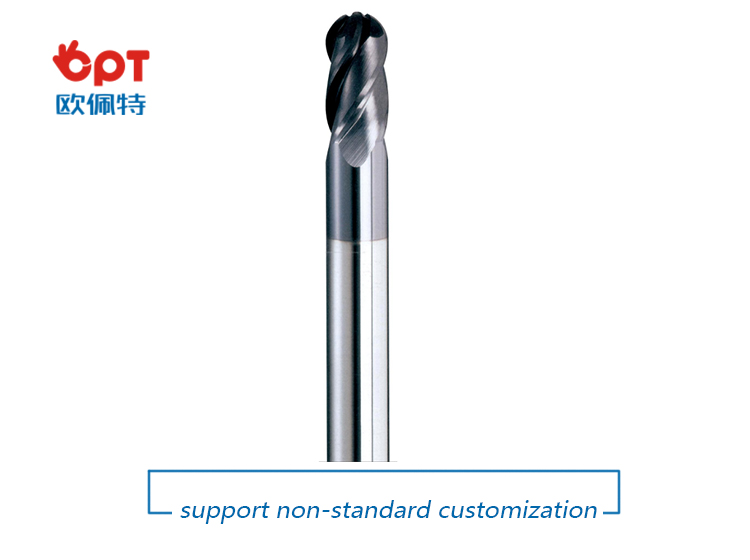
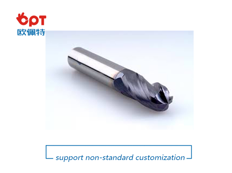
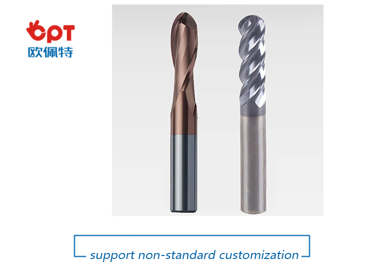
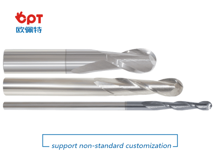
Ball nose end mills is designed for machining molds and
complex curved surfaces. It is also the most commonly used tool for NC
milling machines and machining centers. With the wide adoption of numerical
control technology, the demand of ball nose end mills are increasing
continuously.
Advantage:
One tool for many materials as well as hardened steel
Cost effective tools
Features
2 or 4 flute solid nose ball end mills
Roughing as well as finishing cutters
A selection of various coating
Suitable for regrinding
Flexible in order quantity:
Samples can be provided before mass production, and MOQ can be discussed accordingly.
PRODUCT DETAIL:
PRODUCTING PROGRESS:

PAYMENT AND DELIVERY:

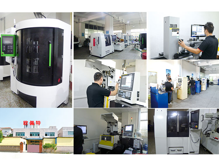
PRODUCT EQUIPMENT :
ABOUT US :
We are specialize in manufacturing PCD diamond tools and Carbide tools. Our major product inclulde PCD Inserts , PCD Reamers , PCD End Mills, PCD Taps, Cabide Inserts,Carbide Drills, Carbide Reams, Taps etc.,
We also offered customized cutting tools per drawings, and provide package according to customer requirements. We manufacture a series range of cutting tools for machining of Cast iron, Aluminium alloy and Non-Ferros metal, it is widely used in all major sectors like Automobiles, Engineering, Aerospace, Aviation and 3C industry. Premium quality of raw material is used in the production and strict examination during processing with advanced equipment, so our client are satisfied with our reliable quality and on-time delivery.
Our best selling of cutting tools include PCD Inserts, PCD End Mill, PCD Ball Nose Mill, PCD Reamer, Carbide Taps, Carbide End Mill, Special Form Cutter and many more. For these years we have been made a large forward in the technologies of manufacturing cutting tools. With high quality on performance and price, our product sells well both on domestic and overseas market. And we will always focus on the quality and best service, to make long business relationship.

quanlity control:
We have dedicated team of quality control and precise equipment to keep good and stable performance for our products and processing services.

Ball End Mill,Ball Nose End Mill,Bull Nose End Mill,Carbide Ball End Mill
OPT Cutting Tools Co., Ltd. , https://www.optdiamondtools.net
