During the school project, the author was involved in the processing of thin-walled components. The CNC machine tool used was the CK7525 (manufactured by Baoji Machine Tool Co., Ltd.) with a FANUC 0i control system. Through this experience, the author gained valuable skills in machining thin-walled hole parts. The part in question is shown in Figure 1 and is a critical component used in aviation machinery. It features a large diameter and extremely thin walls, with the minimum wall thickness being as low as 2.16 mm. This makes the machining process highly challenging due to the high precision requirements and the material properties.
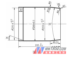
The material used for the part is 2024 aluminum alloy, which is known for its high strength, good fatigue resistance, and excellent cutting performance. However, it also has poor corrosion resistance. The thin-walled structure combined with the large diameter makes the machining process particularly sensitive to deformation caused by cutting forces and heat. To overcome these challenges, a detailed processing plan was developed, including custom fixtures and specialized tools. This paper outlines the entire machining process, focusing on process analysis, fixture design, and specific machining steps.
Process Analysis
This part is classified as a thin-walled rotating component. To ensure accuracy and minimize deformation, the machining process was divided into several stages. First, roughing was performed on a horizontal lathe, followed by semi-finishing and finishing on a CNC lathe. Several key factors were considered during the process planning:
(1) Due to the thin walls, the workpiece was clamped at a longer section (about 50 mm beyond the final length) to avoid deformation during clamping.
(2) A new jig was designed to hold the workpiece securely without causing distortion under cutting forces.
(3) Because of the large diameter, significant heat was generated during cutting, leading to potential thermal deformation. Therefore, careful temperature control and cooling were essential throughout the process.
2. Machining Process
After extensive trials and process optimization, a stable and effective machining procedure was established:
(1) In the blanking stage, a sleeve with an outer diameter of φ270 mm and inner diameter of 230 mm was used, with a total length of 250 mm (including a 50 mm clamping area).
(2) Rough machining was carried out on a horizontal lathe to ensure flat end faces and accurate length (247 mm), while also machining the tapers of the inner and outer surfaces.
(3) Heat treatment was applied to relieve internal stresses and improve the mechanical properties of the workpiece.
(4) Semi-finishing was done on a CNC lathe, using a tailstock to support the right end of the workpiece. Sufficient cooling was maintained, and anti-deformation jaws were used during clamping.
(5) After semi-finishing, the workpiece underwent aging treatment to further reduce internal stress.
(6) A plastic ring was placed around the outer surface, and the inner cavity was semi-finished.
(7) Another aging treatment was conducted after the semi-finishing of the inner cavity.
(8) The final finishing of the inner cavity was completed using the same plastic ring setup.
(9) A final aging treatment was performed before the last clamping step.
(10) The workpiece was re-clamped using a custom fixture for the final finishing to achieve the required dimensions.
(11) The workpiece was cut using a 1 mm wide blade to prevent radial deformation during the final cut.
Due to the thin walls and large diameter, continuous machining in one setup would lead to excessive heat buildup, affecting dimensional accuracy. To mitigate this, the finishing process was performed at a lower speed, and semi-finishing and finishing were separated. Additionally, the inner and outer surfaces were machined in different setups, with constant monitoring of temperature changes to maintain accuracy. Aging treatments were also included after each major machining stage to eliminate residual stresses.
3. Fixture Design
Considering the relatively small batch size, two types of auxiliary fixtures were designed: a simple plastic ring and a basic support fixture. Their functions are as follows:
(1) Plastic ring clamping and turning (see Figure 2). One plastic ring was placed in the center of the workpiece to prevent the inner hole tool from deforming the wall. Another ring was positioned at the front end’s arc to prevent deformation during feed operations.

(2) A simple auxiliary fixture was designed for the outer circle finishing (see Figure 3). During clamping, the mandrel was inserted into the CNC machine spindle, followed by the workpiece placed in a self-centering chuck. A slight clamping was applied, then a plastic washer and a tapered mandrel were added. An aluminum pad connected to a spring block was placed on top, and finally, the tailstock was used to secure the workpiece. Care was taken not to apply too much force to avoid deformation.

4. Machining Steps
To meet the precision requirements, two programs were written for semi-finishing (shape and cavity), and two more for finishing (shape and cavity). One program was also created for the final cutting operation. The steps were as follows:
(1) Semi-finishing the shape of the thin-walled part. With a machining allowance of about 6 mm, the process was split into two passes (3 mm each) to avoid uneven stress distribution and errors.
(2) Semi-finishing the inner wall. A plastic washer was used to cover the workpiece, and the inner cavity was machined in two steps (3 mm each) by adjusting the tool offset.
(3) Finishing the inner cavity. The same plastic washer was used to protect the thin walls while achieving the final dimensions.
(4) Finishing the outer shape. A custom fixture was used to clamp the workpiece and complete the final shaping.
(5) Cutting the workpiece to the required length. A 1 mm wide cutting blade was used to minimize radial force and prevent deformation.
5. Conclusion
Through practical production, the clamping fixtures proved to be structurally sound, providing reliable positioning, uniform clamping force, and high rigidity. They are versatile, easy to use, and significantly improved cutting efficiency while reducing labor intensity. The success rate of this method exceeded 98%, fully meeting the design specifications and greatly enhancing production efficiency.
Living Room Furniture,Dresser Drawer,Aluminum Dresser Drawer,Storage Boxes Bins
Changzhou Offistyle Furniture Co., Ltd. , https://www.offistylefurniture.com