2 Author brief introduction Chen Yongguang lecturer, doctoral student. Mainly engaged in the teaching and research of military oil equipment 6纟; Abstract This paper applies CADCAECAM integrated software IDEAS to a hydraulic press table and upper beam in working condition. 0 Introduction A certain type of hydraulic machine is a medium-sized pressure device with complex structure and force. Larger, the workbench and the beam + only the self, the role of the cylinder and hydraulic pressure, therefore, the strength of the table and the beam has a great impact on the performance and safety of the entire hydraulic machine. Using the finite element analysis method, it is possible to calculate and simulate the structure, decompose the deformation and stress distribution at the initial stage of product development, so that the design can fully understand its strength before it is put into production, and it can make inadequacies.
Improvements, which shorten the design trial cycle and save a lot of experiment and production costs.
In order to analyze the optimization of the force and deformation of the workbench and the upper beam under working conditions, this paper uses 45 software to analyze it in detail on the 501 workstation, which provides a basis for the structural improvement and optimization design of the hydraulic machine.
1 Body structure and finite element model 1.1 The structure of the machine body is the base of the hydraulic machine, which plays the role of the whole machine and the hydraulic pressure. The main structural parameters are length, width and height = material 0019601700 legs, total 屯1200001 skill, the village material is , 5 steel, its structural entity feeding the above beam to support the hydraulic cylinder, the main structural parameters are length and width 1 height = 240,96,1700 pan, total weight 100000 material is 9235 steel, its structural solid model 3.
1.2 Finite element calculation model Since the structure and load of the workbench and the upper beam are symmetrical to the longitudinal and lateral central planes of the body, a 14-body finite analysis model is established. The mesh partitioning unit uses a node plane unit. The workbench has a total of 3164 nodes, units 13, 45, and 2; the upper beam has 2197 nodes, and the unit is 6473.
1.3 Boundary conditions, the pressure of the pressure-bearing pier acts perpendicularly on the work surface, a total of 400 tons, evenly distributed, the direction is downward, the tension at the support of the column is 8 places, each 100 tons, the ring distribution, the direction is upward, the hydraulic cylinder force is two The big circle is respectively subjected to a force of 121.5 tons, with a circular distribution and a downward direction. The two small circles are respectively subjected to a force of 78.5 tons, and the ring is distributed and the direction is downward.
The table constraints are mainly ground support and applied to the bottom surface and the symmetry plane according to the symmetry. The upper beam constraint is mainly applied to the symmetry plane according to the symmetry. Workbench and upper beam boundary conditions 3 and 315.
2 Calculation results analysis Computer-aided engineering 2.1 Workbench stress and deformation Workbench stress and deformation 4, the stress is mainly generated in the central support hydraulic cylinder of the workbench, the maximum value is generated at the central symmetry of the ring top, its value is 96.613., the maximum The deformation occurs at the support table near the support of the column, and the maximum deformation is 2. From the calculation results, the maximum stress of the table is obviously smaller than the allowable stress of the material and the deformation is small, and the tenth meets the requirements.
04a table stress and deformation 2.2 upper beam stress and deformation 1 upper transverse force è’‰ shape 4 æ™·, the stress is mainly generated in the upper beam of the central branch of the withdrawal cylinder, the maximum is generated at the ring, its value is 12613, the largest The deformation is generated at the ring of the supporting hydraulic cylinder, and the maximum deformation is 42.
From the calculation results, the maximum stress of the upper beam is smaller than the allowable stress of the material and becomes smaller, and the design meets the requirements.
3 Conclusions No.4 hydraulic machine table and upper beam finite element analysis 宄67 finite element model of the establishment of boundary conditions and meshing calculation results analysis and evaluation. It can be seen from the analysis results that under the action of the actual working load, the stress of these two components is less than the allowable stress of the material, and the deformation is very small, satisfying the design and use requirements, referenced by Liu Xianji, et al. 5 advanced. Science Press, 2001.4 Fangxin compiled. 1 Product dimension design guide. Mechanical Industry Press, 2000.
10. Cook. The concept and application of finite element analysis. Science Press, 1981
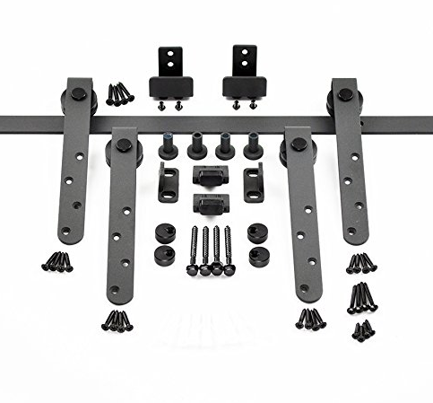
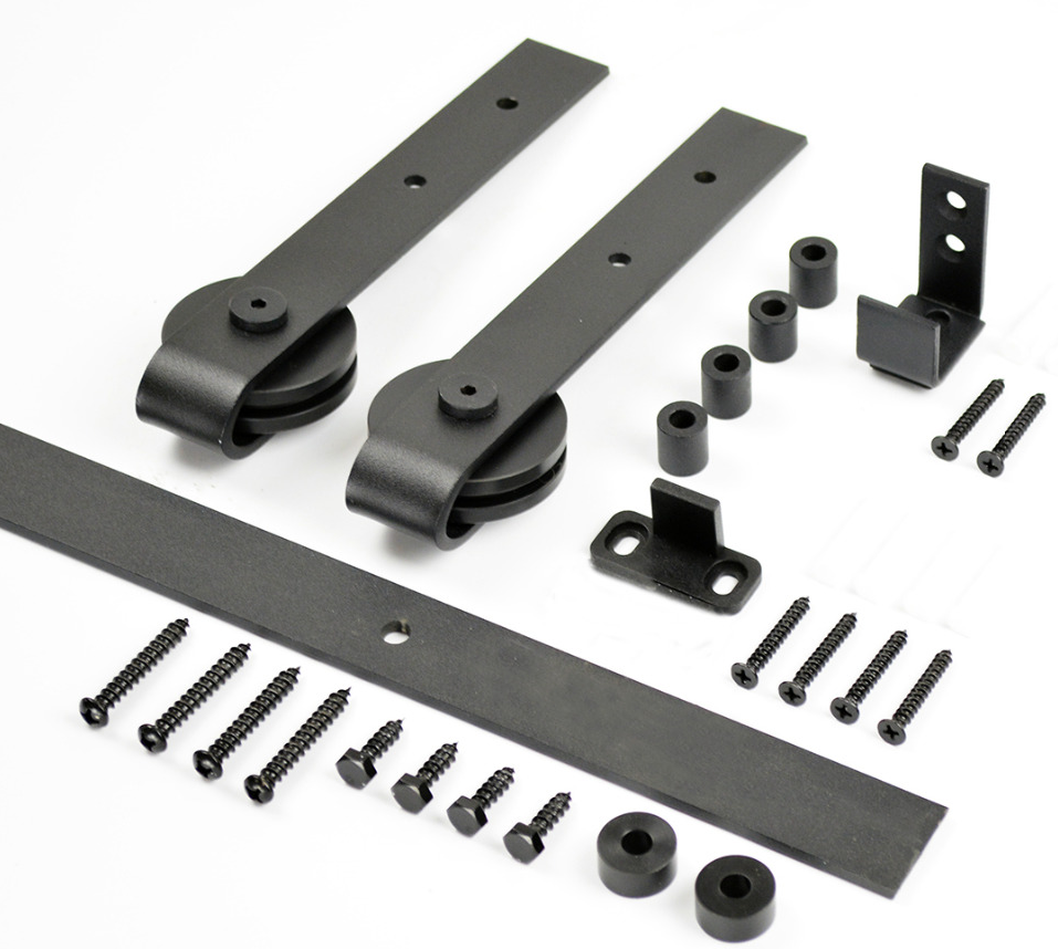
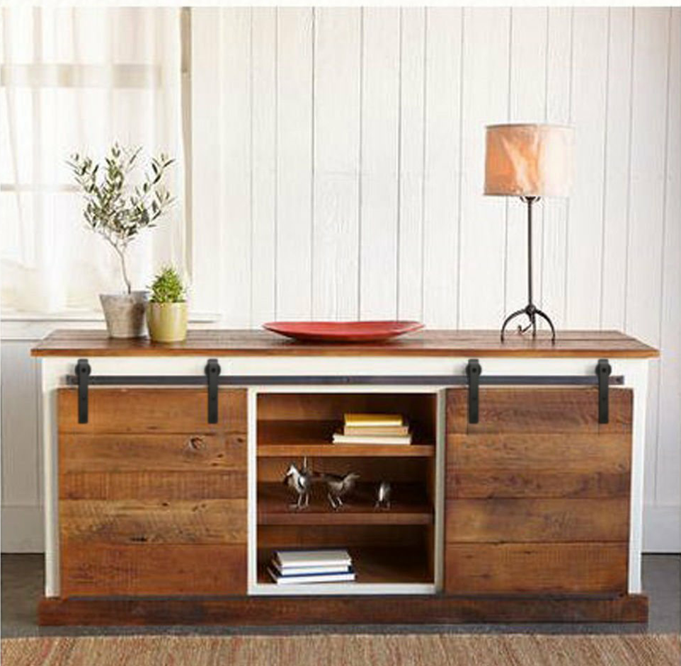
Our mini Sliding Door Hardware kit can be used for various purposes such TV stand door, vanity door replacement, cabinet renovation, add on to your pet`s kennel, bookshelf closet and so on!
The Material is carbon steel to make the hardware heavy-duty and sturdier than the competition. The black powdered coating makes the paint stays forever and will not be scratched off. The wheels of the roller are made of high-quality nylon which ensures minimal noise when it glides on the track. Each complete track can hold door weight up to 100 lbs.
Of course you can customized size and color you like.


Mini Barn Door Hardware,Mini Barn Door Hardware For Cabinets,Barn Door Hardware For Cabinets,Mini Sliding Barn Door Hardware,Mini Barn Door Kit
Foshan Nanhai Xin Jianwei Hardware Co., Ltd , https://www.aaghardware.com